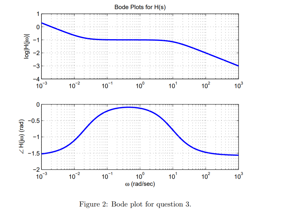

The first step on how to setup bode plot in Simulink is to have your model ready. Figure 1 How to Setup Bode Plot in Simulink – Step by Step Procedure 1. Higher versions of Matlab may have slight different interface and you need a little exploration. Also in this tutorials I used Matlab R2012b. To demonstrate this properly, consider the Simulink model in Figure 1. You should have license for Simulink control design to use the bode plot. In a bode plot you can get the gain and phase margins and know if the system is stable or not. Bode plot is a graph of gain and phase of a system. In terms of circuits this means we might have a \(V_\) (depending where the constant lies.Below is the step by step procedure on how to setup bode plot in Simulink. Generally a transfer function is equivalent to the ratio of an output to an input. Usually denoted as \(H(s)\) or \(H(j\omega)\). Q: What do we need to start doing the Bode Plots?Ī: The first thing we’ll need is called transfer function. One we’ll call the magnitude plot and one called the phase angle plot. In this set of notes we will call \(\omega\) our input frequency.īode plots typically consist of two graphs. This system could be any system (not just a circuit!) which experiences change in behavior due to a change in frequency (cycles/second).įrequency Response basically means how our system will change with respect to a given input frequency. Let’s get started by first answering a few questions.Ī: Bode plots are a actually a set of graphs which show the frequency response of a system. But we will cover the basics of how to bode plots for both magnitude and phase angle, explaining each step along the way. The aim of this page is to explain Bode plots as simply as possible. A Beginner's Guide to Bode Plots Zac Blanco Blog Education Projects About A Beginner's Guide to Bode Plots


 0 kommentar(er)
